When a hydraulic circuit starts acting up—slow implements, erratic pressure readings, or fault codes—the pressure sensor is often blamed first. But replacing a sensor without a proper diagnosis can waste time and money. Industry data suggests that 60-70% of reported "sensor failures" actually stem from installation errors, environmental factors, or system issues rather than the sensor itself (source: SUCO ESI). This guide walks you through a practical, step-by-step diagnostic process to pinpoint the real culprit and get your equipment back to work.
What percentage of reported "sensor failures" are actually caused by installation errors, environmental factors, or system issues, according to industry data?
Select one answer.
Start with the Symptoms, Not the Sensor
Before you reach for a multimeter, gather information. A sudden loss of pressure, a gradual drift in readings, or an intermittent fault code point to different root causes. Check the system schematic and trace the flow. Ask yourself: Did the problem appear suddenly or over time? Is there unusual noise or heat? This initial step can cut troubleshooting time in half (source: Machinery Lubrication).
Common pressure sensor failure symptoms include inaccurate readings, signal drift, no output, intermittent output, excessive noise, and slow response (source: Saftty). But these same symptoms can also be caused by wiring faults, power supply issues, or a blocked pressure port.
Isolate the Sensor from the System
A key principle is to determine whether the problem is in the sensor, the wiring, or the control system. Disconnect the sensor from both the process and the control system, then test it independently (source: SUCO ESI). This isolates the sensor and prevents other system components from masking the issue.
Test with a Multimeter: Step-by-Step
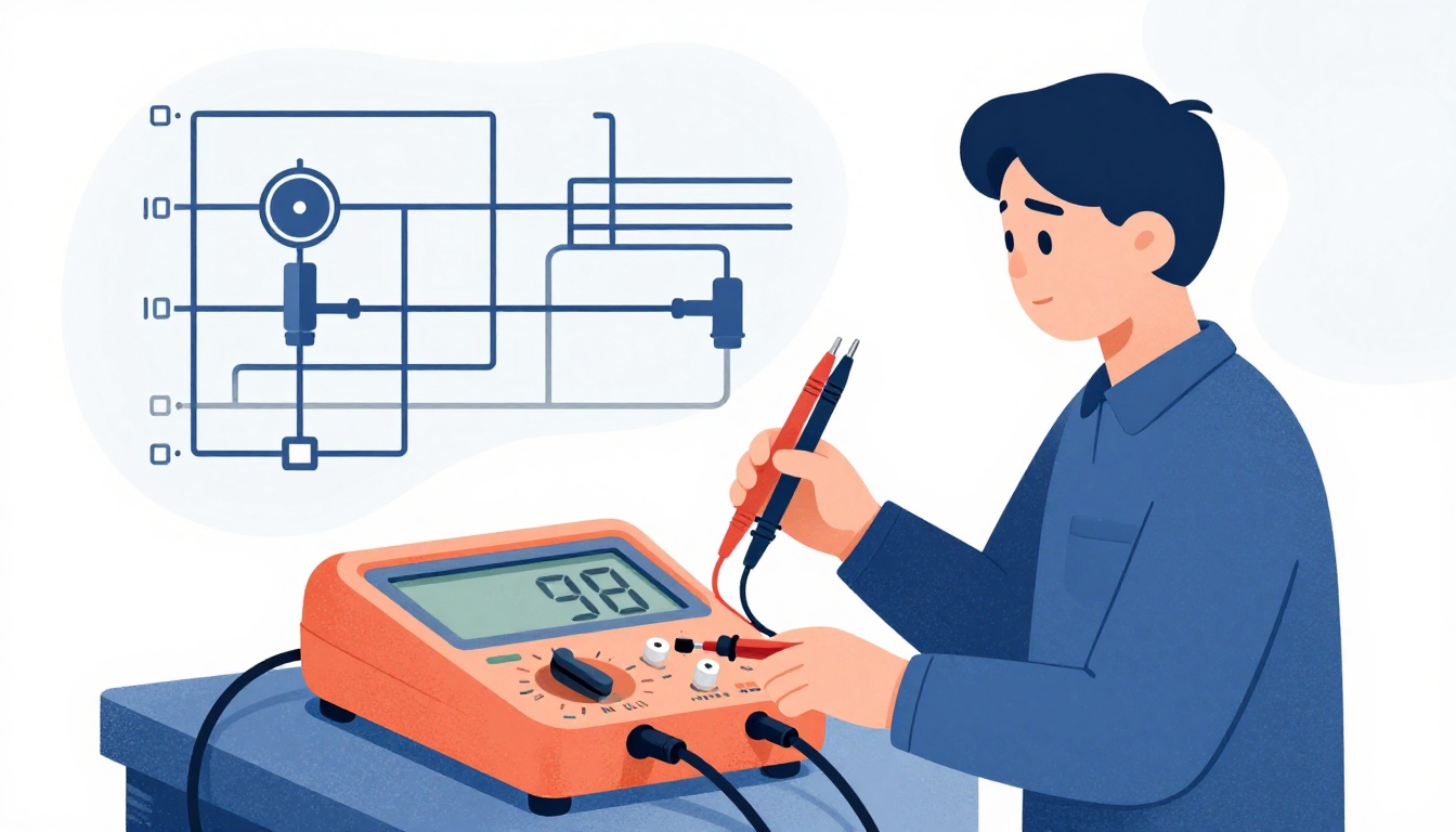
A digital multimeter (DMM) is your primary tool for field diagnostics. Here’s a practical sequence:
- Verify power supply: Check that the sensor is receiving the correct excitation voltage (e.g., 5V, 12V, or 24V) at the connector. A bad power supply can cause erratic readings.
- Inspect wiring and connectors: Look for damaged cables, loose connections, or corrosion. A poor connection can cause intermittent signals or a "circuit high" fault (source: Facebook group discussion).
- Measure the output signal: Connect the multimeter to the sensor output. At zero pressure, the output should match the manufacturer's no-load specification (e.g., 0.5V for a 0.5-4.5V sensor). If not, the sensor may be faulty (source: ES Systems).
- Apply a known reference pressure: Use a hand pump or calibrated pressure source to apply a known pressure. Compare the sensor output to the expected value from the datasheet. This checks calibration and full-scale response.
- Check for shorts and continuity: Use the multimeter's continuity and resistance modes to check for short circuits to ground or power, and verify the integrity of the sensor's internal bridge circuit (source: SenTec).
For 4-20mA sensors, you can place a 250Ω resistor in series and measure the voltage across it to infer the current (source: ES Systems).
Common Culprits Beyond the Sensor
If the sensor tests fine, look elsewhere:
- Wiring and connectors: A short to power or ground in the wiring can cause a "circuit high" fault (source: Facebook group discussion).
- PLC input noise: Measure the signal at the sensor and then at the PLC input. If the signal is clean at the sensor but noisy at the PLC, the issue is likely electrical interference or grounding (source: WHYPS).
- Blocked pressure port: A clogged or restricted port can cause slow response or inaccurate readings.
- System pressure problems: Low system pressure may be due to a faulty pump or relief valve, not the sensor. Use a mechanical gauge to verify actual system pressure (source: Machinery Lubrication).
When to Repair or Replace
If the sensor is truly faulty, you have options. Replacing a sensor is straightforward, but for complex hydraulic systems, consider a repair service that specializes in electronic controls. A professional diagnostic service can test the sensor and the entire control circuit, saving you from repeated failures.
Quiz: Test Your Diagnostic Knowledge
Question: What percentage of reported "sensor failures" are actually caused by installation errors, environmental factors, or system issues, according to industry data?
- 10-20%
- 60-70%
- 90-100%
Correct Answer: 60-70%
How the Featured Expert Can Help
If you're facing persistent hydraulic pressure sensor issues, RE-CLICK offers electronic control repair and diagnostics for heavy equipment, including sensors, joysticks, and ECUs. Their certified technicians provide nationwide support, aiming to reduce downtime and extend equipment life. Call them for fast, reliable service on your control circuit boards and sensors.